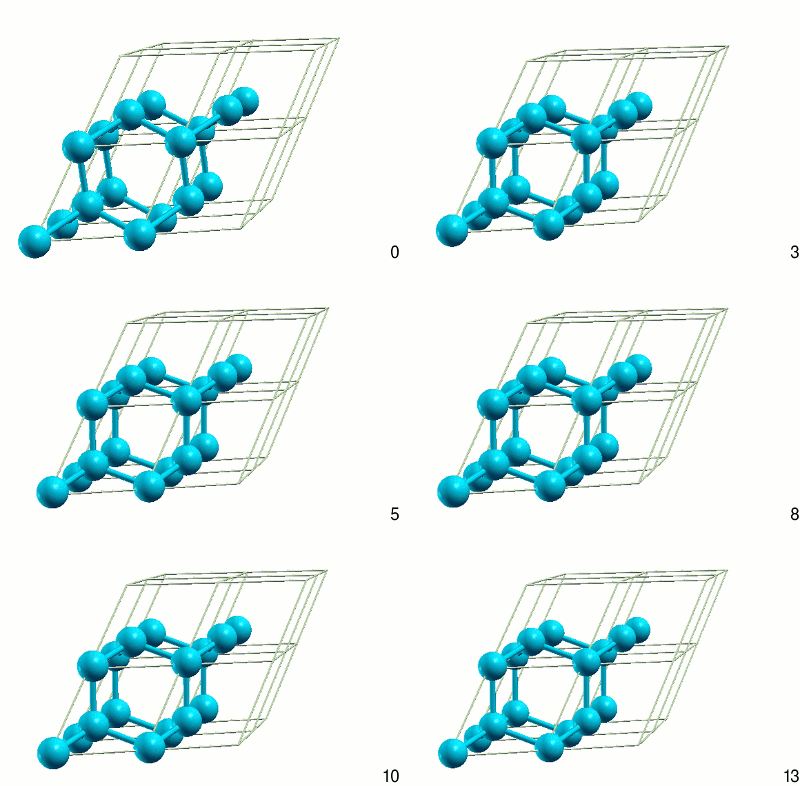
The previous tutorials have calculated properties of silicon at fixed geometry, which in the case of a crystal includes the ionic positions as well as the lattice vectors. To optimize the ionic positions at fixed lattice vectors, command ionic-minimize suffices as in the molecular cases (see the Geometry optimization tutorial for example). This tutorial introduces lattice optimization using the lattice-minimize command.
We'll start with the essentially the same input as the previous tutorials, but in order to test the minimizer, we'll artificially introduce a strain:
#Save the following to Si.lattice
lattice face-centered Cubic 11.3   #this is deliberately about 10% too large
Write the ionic positions to a separate file:
#Save the following to Si.ionpos
ion Si 0.00 0.00 0.00  1
ion Si 0.30 0.30 0.30  1   #deliberately perturbed (should have been 0.25)
and create the input file for lattice optimization:
#Save the following to latticeOpt.in
include Si.lattice
include Si.ionpos

kpoint-folding 8 8 8
ion-species GBRV/$ID_pbe.uspp
elec-cutoff 20 100

electronic-SCF                   #Electronic state optimization
lattice-minimize nIterations 10  #Lattice and ionic geometry optimization
dump-name Si.$VAR
dump Ionic State                 #Output state every geometry (ionic/lattice) step
For silicon, symmetries completely determine the internal geometry (fractional ion coordinates), but in order to illustrate a more general situation, the above input starts from a perturbed internal geometry as well. Lattice minimization updates both the lattice vectors and the internal geometry; the internal geometry can be constrained using zero moveScale factors in command ion.
Run JDFTx on this input file a few times:
mpirun -n 4 jdftx -i latticeOpt.in | tee latticeOpt.out
mpirun -n 4 jdftx -i latticeOpt.in | tee -a latticeOpt.out
Note that each run updates both Si.lattice and Si.ionpos, so that the next one starts at the final geometry of the previous one. However, we deliberately do not read in the wavefunctions of the previous run (using initial-state) in the subsequent runs. Once the lattice changes, the plane-wave basis within the specified kinetic energy cutoff will change making the wavefunctions incompatible.
Within each run, the basis is kept constant because otherwise the energy would change discontinuously with varying lattice vectors, making it impossible to use an efficient minimization algorithm. However, this means that the basis is inconsistent with the original elec-cutoff once the lattice vectors have changed from the input value. This is why it is essential to rerun lattice optimizations a few times, especially if the initial strain is large, and stop when the lattice changes negligibly (around 0.1%) in a given run. (This issue can be mitigated partially using Pulay corrections - see script calcPulay - but it is important to continue the lattice minimization over a few runs regardless.)
Examine the output file. Note that the usual IonicMinimize output is now replaced by LatticeMinimize, with the overall structure of the output remaining very similar. The |grad|_K reported by LatticeMinimize includes both the forces and the stresses (with the stresses brought to the same dimensions as the forces by scaling with the unit cell dimensions). Additionally, LatticeMinimize reports the lattice vectors, strain and stress at every step, in addition to ionic positions and forces.
Note that in the present case, the first run ends with a strain of -8.6%, while the second run ends with a strain less than 0.001%, so we can stop after the second run; but often more runs could be necessary. You can also visualize the convergence of the energy using the plotConvergence script. By default "plotConvergence latticeOpt.out" will plot the convergence every electronic iteration, but you can use "iterType=Lattice plotConvergence latticeOpt.out" to examine the convergence with lattice opimization steps.
Check the final lattice vectors and internal geometry (Si.lattice and Si.ionpos). The final lattice is face-centered Cubic with a cubic lattice constant of 10.33 bohrs, which is only 0.7% larger than the experimental value of 10.263 bohrs (typical accuracy for the PBE exchange-correlation functional). Note that the ionic positions have a net translation to the ones we specified in previous tutorials: the optimizer moved both Si atoms in the unit cell toward each other to fix the perturbation we introduced. Of course, with periodic boundary conditions and the plane-wave basis, this makes no difference at all. If we wanted to keep the first Si atom pinned to the origin, we could have zero'd its moveScale factor (in command ion).
Finally, we can export the variation of the geometry using
createXSF latticeOpt.out latticeOpt.axsf Animated
and examine the animated XSF file using XCrysDen (since VESTA doesn't support animated XSFs).